Bipolar Transistors
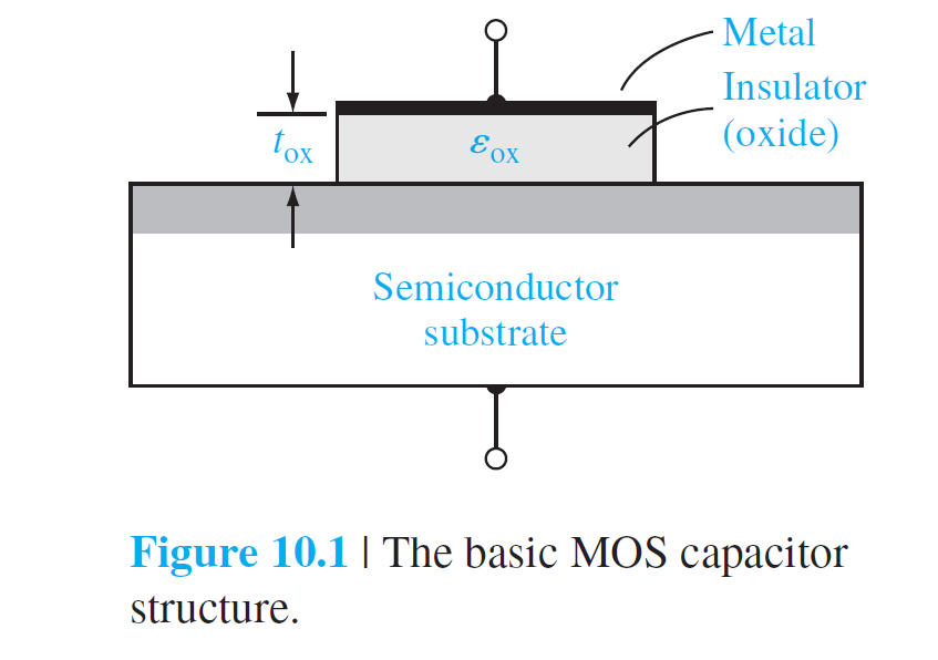
金属-绝缘体-半导体

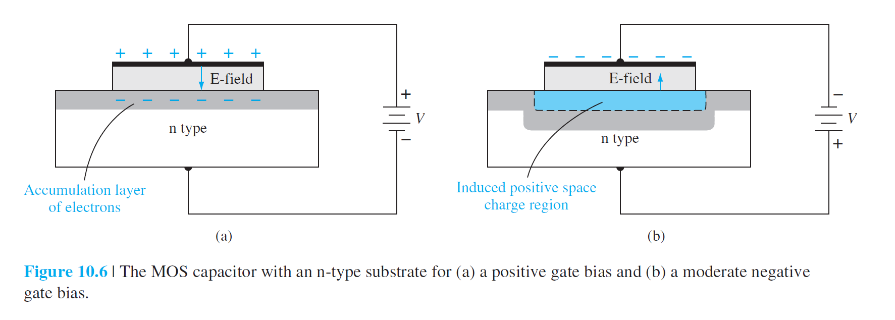
Depletion Layer Thickness
\[
\phi_{fp}=V_t\ln(\frac{N_a}{n_i})
\]
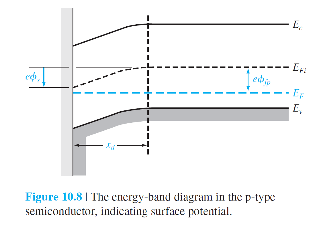
同单边pn结:
\[
x_d=\left( \frac{2\epsilon_s\phi_s}{eN_a} \right)^{1/2}
\]
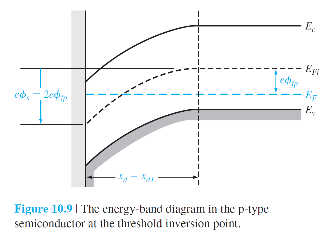
- 表面处的Fermi Level远在本征fermi level 之上
- threshold inversion point 表面出的电子浓度等于体内的空穴浓度,此时所加的电压为:threshold voltage
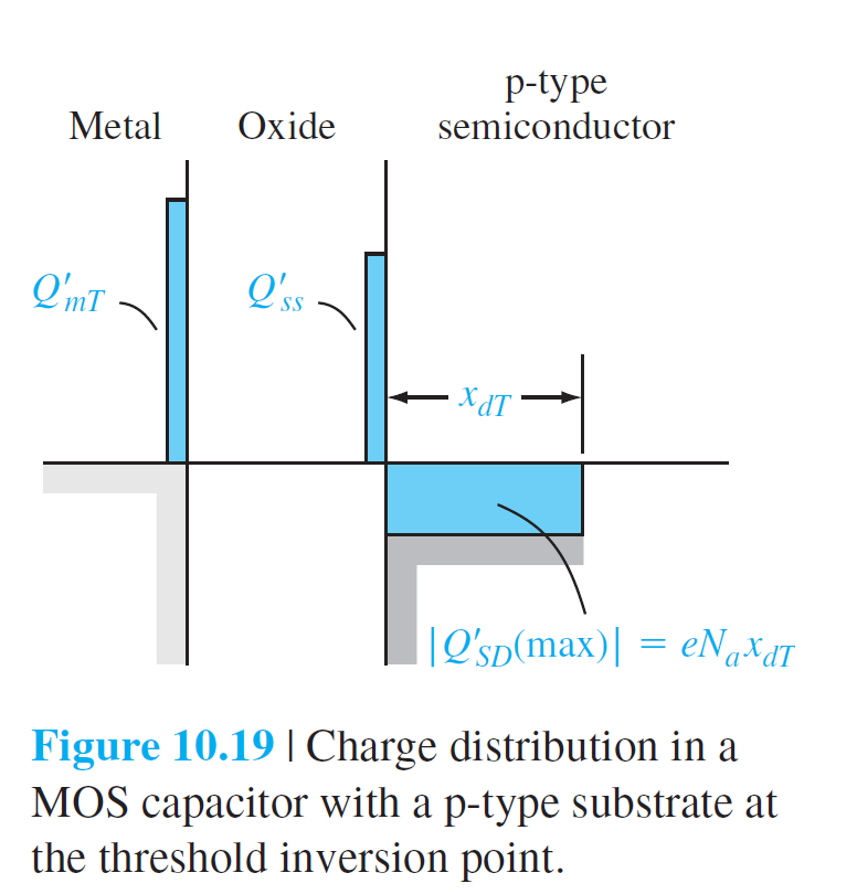
空间电荷区最大宽度\(x_{dT}\)
\[
x_{dT}=\left( \frac{4\epsilon_s\phi_{fp}}{eN_a} \right)^{1/2}
\]
Surface Charge Density
in the conduction band
\[
n=n_i\exp(\frac{E_F-E_{Fi}}{kT})
\]
for a p-type
\[
n_s=n_i\exp(\frac{\phi_{fp}+\Delta\phi_s}{V_t})
\]
- \(\Delta \phi_s\) is the surface potential greater than \(2\phi_{fp}\)
\[
\begin{align*}
n_{st}&=n_i\exp{\frac{\phi_{fp}}{V_t}}\\
n_s&=n_{st}\exp(\frac{\Delta\phi_s}{V_t})
\end{align*}
\]
- \(n_{st}\) is the surface charge density at the threshold inversion point.
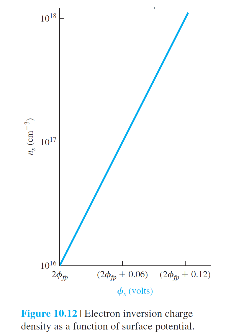
Figure 10.12 shows the electron inversion charge density as a function of surface potential for the case when the threshold inversion charge density is \(n_{st}=10^{16}cm^{-3}\). We may note that the inversion charge density increases by a factor of 10 with a
60-mV increase in surface potential. As discussed previously, the electron inversion charge density increases rapidly with small increases in surface potential, which means that the space charge width essentially reaches a maximum value.
Work Function Differences
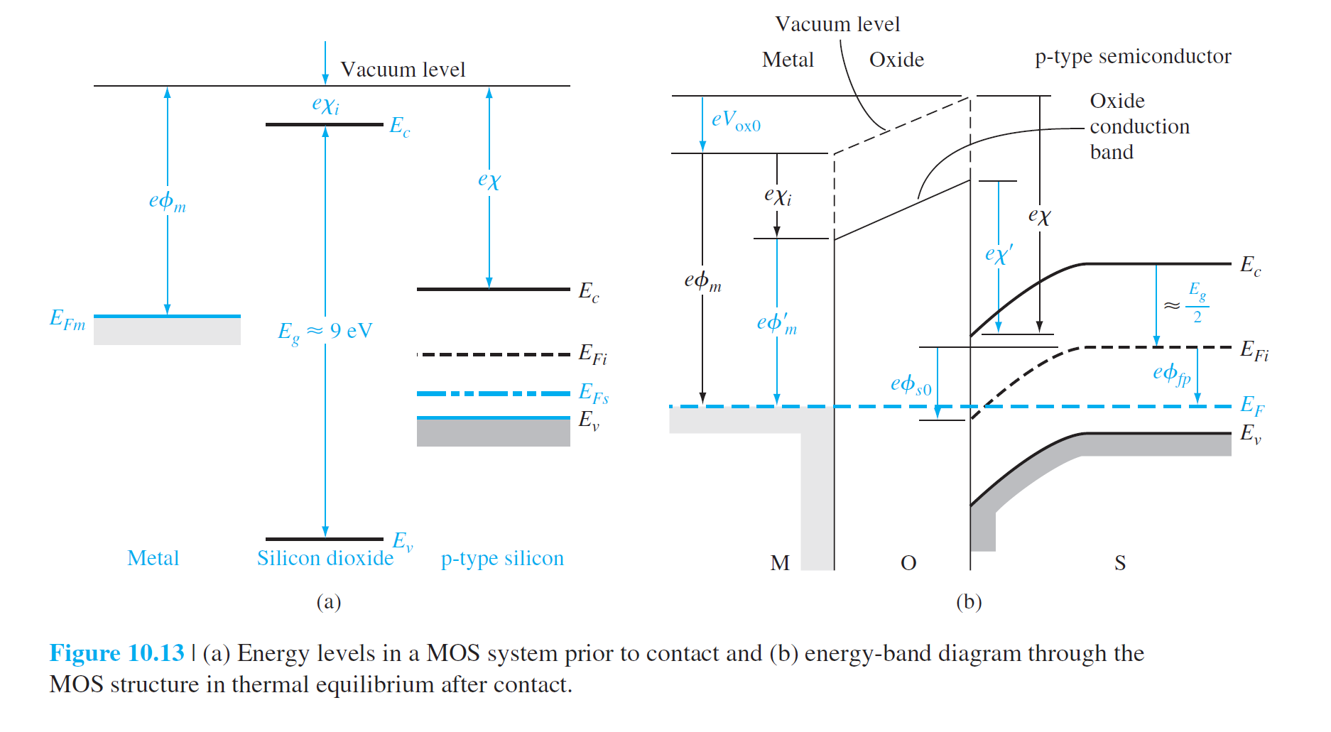
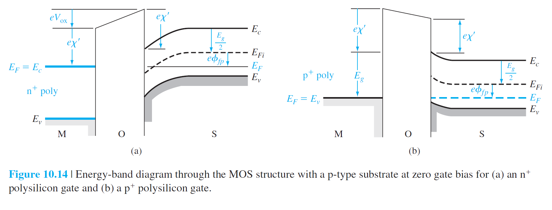
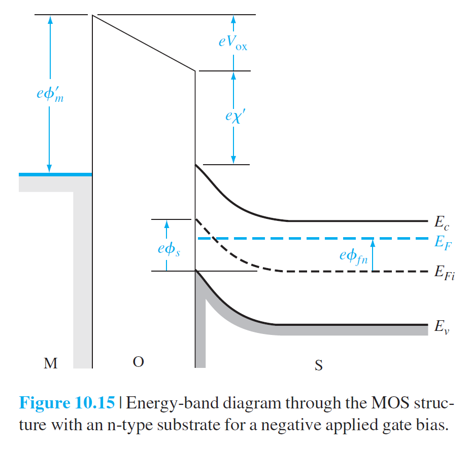
- \(\phi_m\) metal work function - 金属中的电子从金属内部移动到真空所需要的最小能量
- \(\chi\) the electron affinity - 电子从导带底部移到真空所需要的最小能量
- \(\phi_m'\) the potential required to inject an electron from metal into the conduction band of the oxide
- \(\chi'\) modified electron affinity
- \(V_{ox0}\) the potential drop across the oxide for zero applied gate voltage
- \(\phi_{s0}\) the surface potential
\[
\phi_m'+V_{ox0}=\chi'+\frac{E_g}{2e}-\phi_{s0}+\phi_{fp}
\]
\[
V_{ox0}+\phi_{s0}=-\left[ \phi_m'-(\chi'+\frac{E_g}{2e}+\phi_{fp}) \right]
\]
\[
\phi_{ms}=\left[ \phi_m'-(\chi'+\frac{E_g}{2e}+\phi_{fp}) \right]
\]
degenerately doped(重掺杂)
\[
n^+:\quad\phi_{ms}=-(\frac{E_g}{2e}+\phi_{fp})
\]
\[
p^+:\quad\phi_{ms}= (\frac{E_g}{2e}-\phi_{fp})
\]
\[
\phi_{ms}=\phi_m'-(\chi'+\frac{E_g}{2e}-\phi_{fn})
\]
Flat-Band Voltage
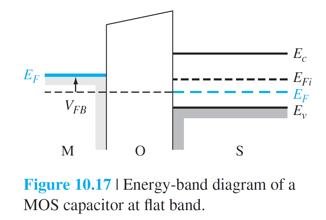
there is no band bending in the semiconductor and, as a result, zero net space charge in this region.
\[
V_G=\Delta V_{ox}+\Delta \phi_s=(V_{ox}-V_{ox0})+(\phi_s-\phi_{s0})
V_G=V_{ox}+\phi_s+\phi_{ms}
\]

\[
Q_m'+Q_{ss}'=0
\]
\[
V_{ox}=\frac{Q_m'}{C_{ox}}=\frac{-Q_{ss}'}{C_{ox}}
\]
平带情况下\(\phi_s=0\)
\[
V_G=V_{FB}=\phi_{ms}-\frac{Q_{ss}'}{C_{ox}}
\]
Threshold Voltage
\[
Q_{mT}'+Q_{ss}'=\abs{Q'_{SD}(max)}=eN_ax_{dT}
\]
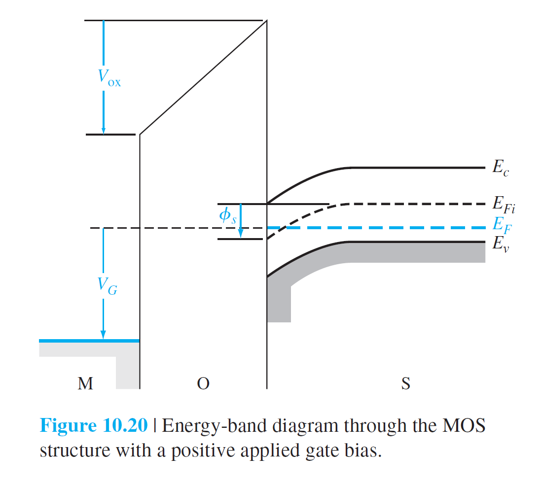
\[
V_G=\Delta V_{ox}+\Delta\phi_s=V_{ox}+\phi_s+\phi_{ms}
\]
在阈值点有\(\phi_s=2\phi_{fp}\)
\[
V_{TN}=V_{oxT}+2\phi_{fp}+\phi_{ms}
\]
\[
V_{TN}=V_{oxT}+2\phi_{fp}+\phi_{ms}
\]
\[
\begin{align*}
V_{oxT}&=\frac{Q'_{mT}}{C_{ox}}\\
&=\frac1{C_{ox}}(\abs{Q'_{SD}(max)}-Q_{ss}')\\
&=(\abs{Q'_{SD}(max)}-Q_{ss}')(\frac{t_{ox}}{\epsilon_{ox}})
\end{align*}
\]
\[
V_{TN}=(\abs{Q'_{SD}(max)}-Q_{ss}')(\frac{t_{ox}}{\epsilon_{ox}})+\phi_{ms}+2\phi_{fp}
\]

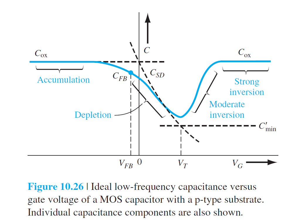
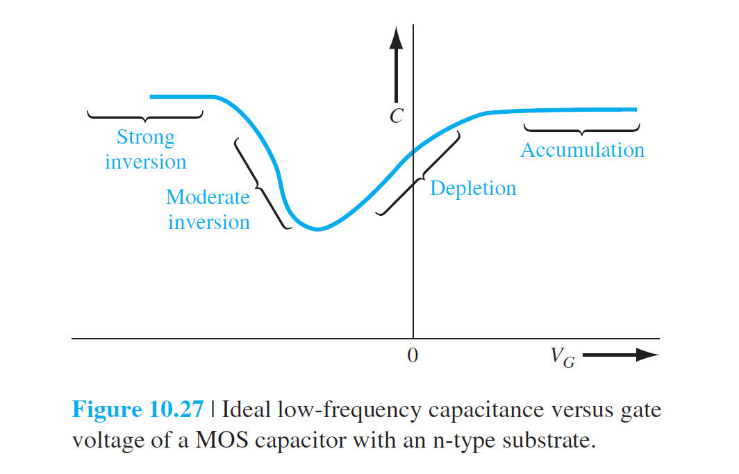
理想C-V特性
堆积 accumulation mode
\[
C'(acc)=C_{ox}=\frac{\epsilon_{ox}}{t_{ox}}
\]
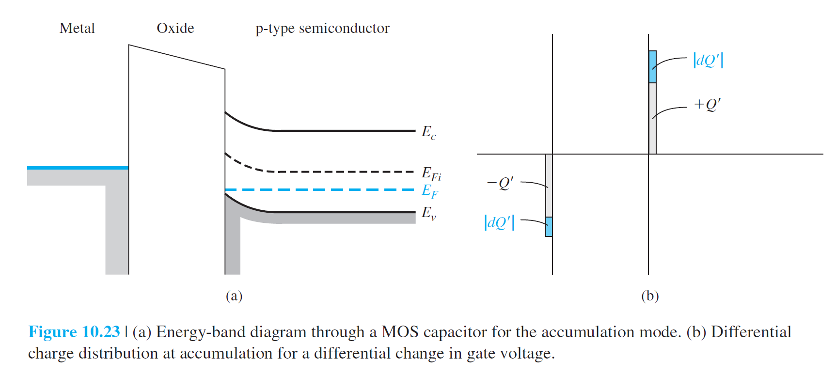
耗尽 depletion mode
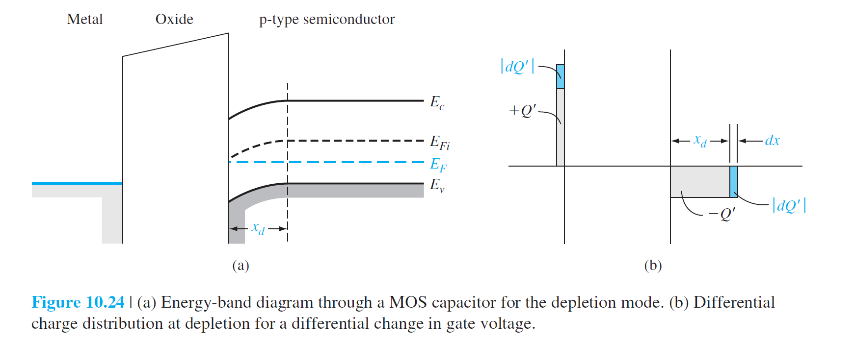
\[
\frac1{C'(\text{depl})}=\frac1{C_{ox}}+\frac1{C'_{SD}}
\]
\(C_{ox}=\epsilon_{ox}/t_{ox}\),\(C'_{SD}=\epsilon_s/x_d\)
\[
C'(\text{depl})=\frac{\epsilon_{ox}}{t_{ox}+\left( \frac{\epsilon_{ox}}{\epsilon_s} \right)x_d}
\]
反型 Inversion Mode
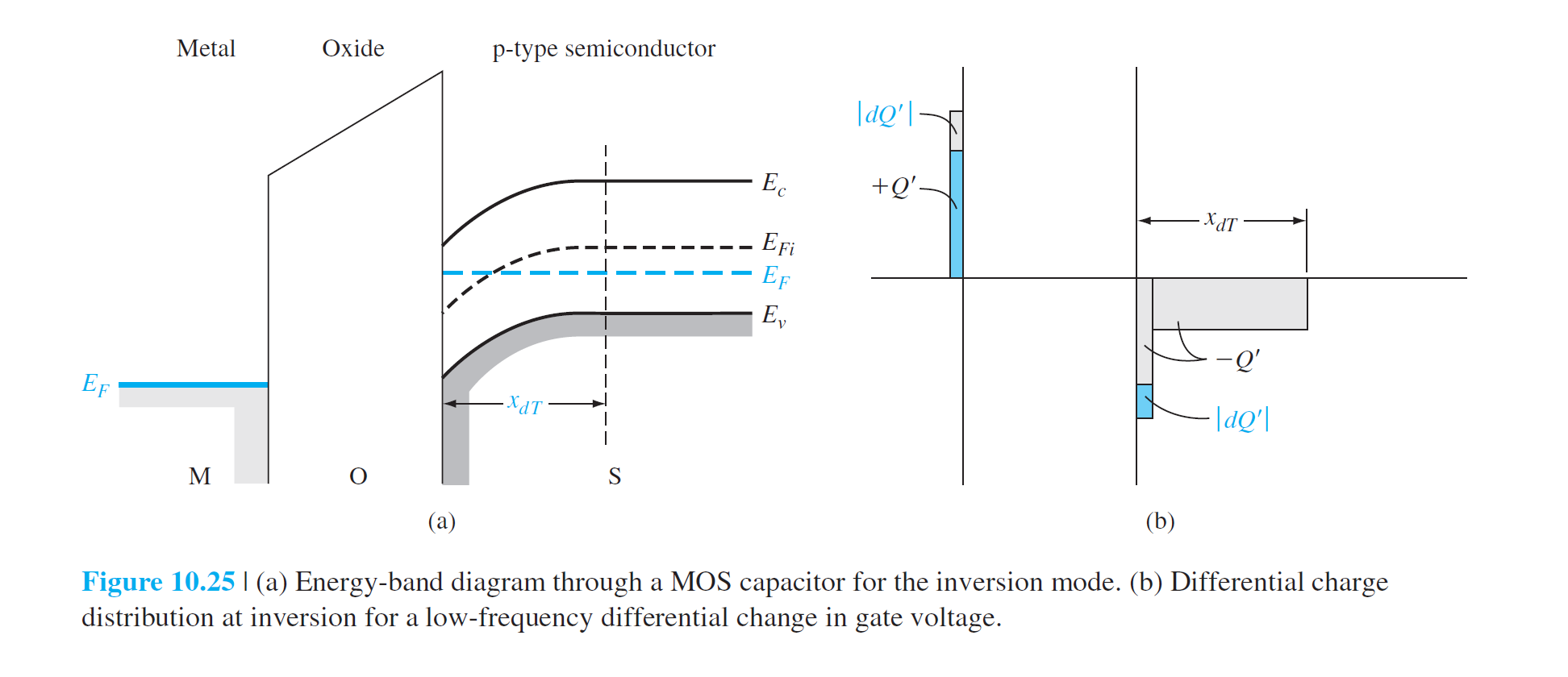
\[
C'(\text{inv})=C_{ox}=\frac{\epsilon_{ox}}{t_{ox}}
\]
\[
C'_{FB}=\frac{\epsilon_{ox}}{t_{ox}} + \left( \frac{\epsilon_{ox}}{\epsilon_s} \right) \sqrt{\left( \frac{kT}{e} \right) \left( \frac{\epsilon_s}{eN_a} \right)}
\]
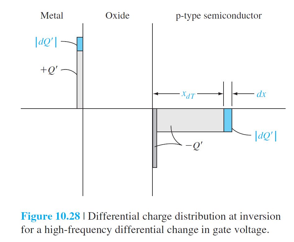
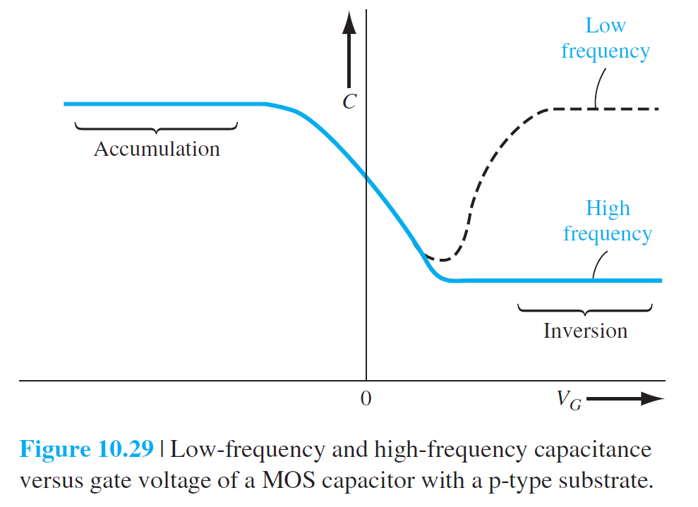
Frequency Effect
The Basic MOSFET Operation
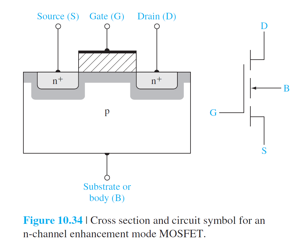


Current–Voltage Relationship—Concepts
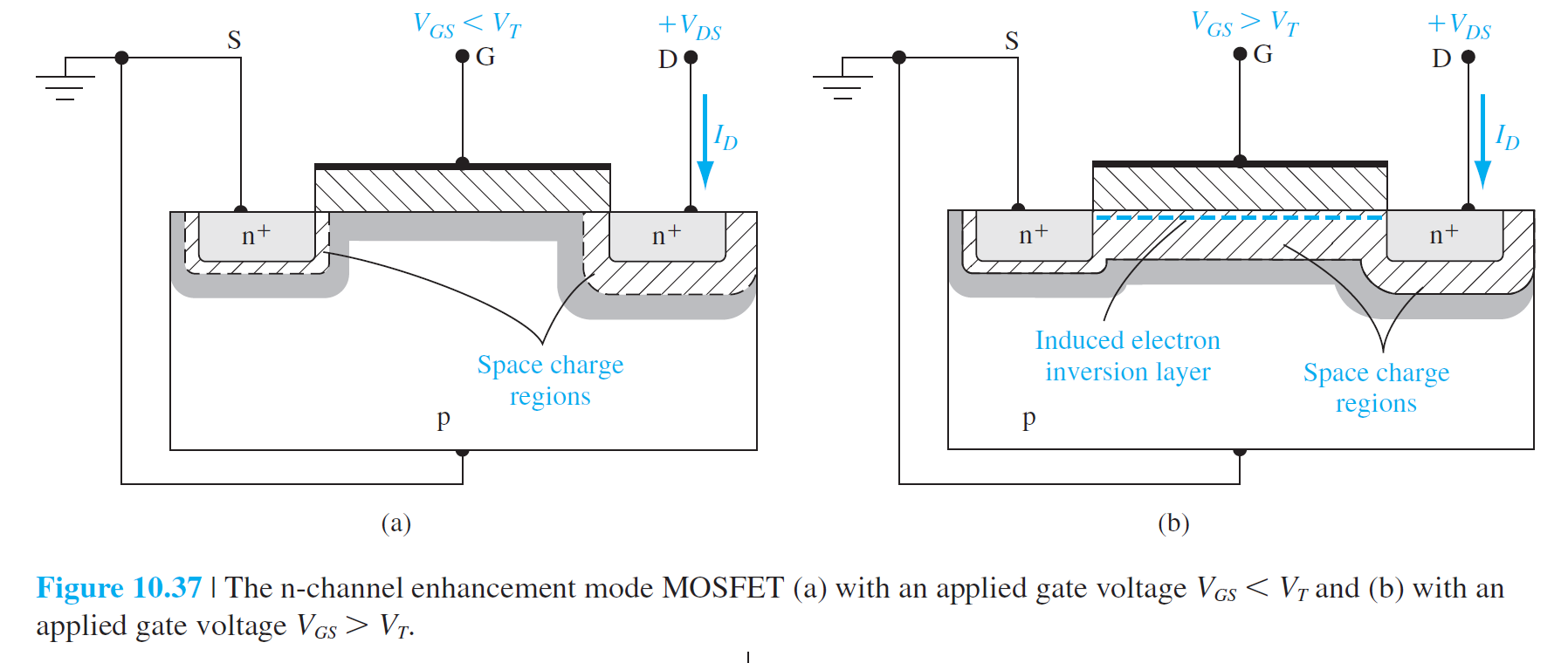
(a):
- Drain极,漏到衬底的pn极是反的,所以漏电流为0,the drain current = 0
(b):
- 电子反型层产生,反型层中的电子从源端流向正的漏端。
- 理想情况下:没有电流从氧化层向Gate流过
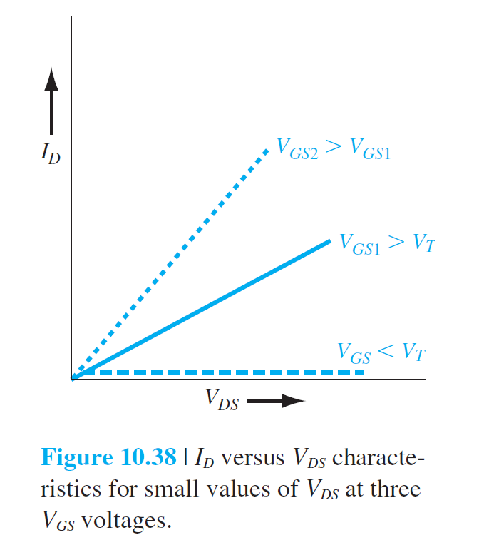
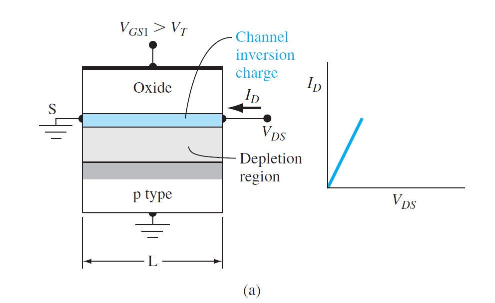
- 对于较小的\(V_{DS}\),沟道有电阻特性
\[
I_D=g_dV_{DS}
\]
\(g_d\)为\(V_{DS}\rightarrow 0\)时的沟道电导
\[
g_d=\frac{W}{L}\cdot \mu_n\abs{Q_n'}
\]
- \(\mu_n\)为反型层中的电子迁移率
- \(\abs{Q_n'}\)单位面积的反型层电荷数量
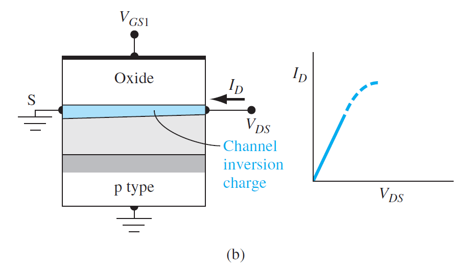
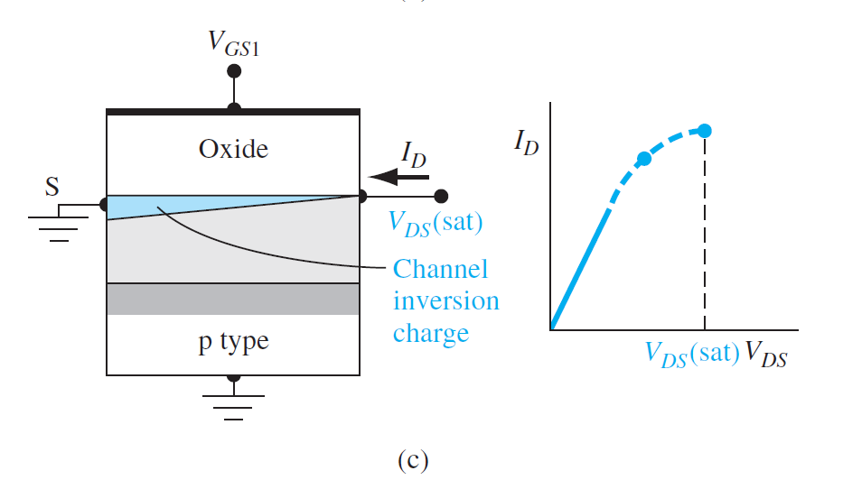
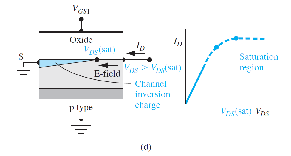

(a): \(V_{DS}\)较小
(b): \(V_{DS}\)增大,漏端附近的氧化层压降减小,漏端附近的反型层电荷密度减小,电导减小,
(c): \(V_{DS}\)增大到漏端的氧化层压降等于\(V_T\)时,漏端的反型电荷密度为0。当电荷为0,电子被注入空间电荷区,并被扫向漏端
\[
V_{DSsat}=V_{GS}-V_T
\]
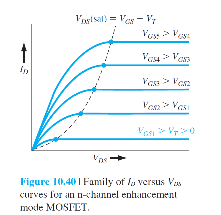

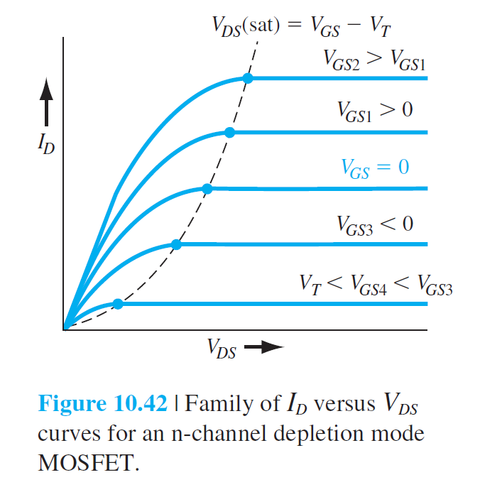
非饱和区:\(V_{GS}>V_T\), \(0<V_{DS}<V_{DS}(sat)\)
\[
I_D=\frac{W\mu_nC_{ox}}{2L}[2(V_{GS}-V_T)V_{DS}-V_{DS}^2]
\]
饱和区:\(V_{DS}>V_{DS}(sat)\)
\[
I_D=\frac{W\mu_nC_{ox}}{2L}(V_{GS}-V_T)^2
\]
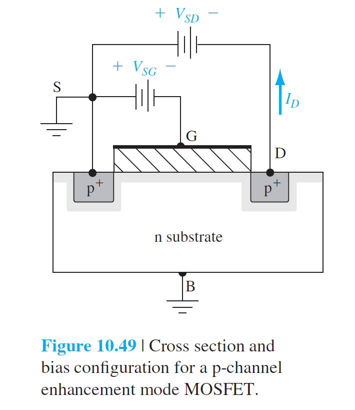
对于p型而言:
\(V_{SG}>V_T\), \(0<V_{SD}<V_{SD}(sat)\)
\[
I_D=\frac{W\mu_pC_{ox}}{2L}[2(V_{SG}+V_T)V_{SD}-V_{SD}^2]
\]
\(V_{DS}>V_{DS}(sat)\)
\[
I_D=\frac{W\mu_pC_{ox}}{2L}(V_{SG}+V_T)^2
\]
跨导 Transconductance
\[
g_m=\frac{\partial I_D}{\partial V_{GS}}
\]
\(g_m\)晶体管增益
\[
g_{mL}=\frac{\partial I_D}{\partial V_{GS}}=\frac{W\mu_nC_{ox}}{L}\cdot V_{DS}
\]
非饱和区,跨导随\(V_{DS}\)线性变化,与\(V_{GS}\)无关
饱和区:
\[
g_{ms}=\frac{\partial I_D(sat)}{\partial V_{GS}}=\frac{W\mu_nC_{ox}}{L}(V_{GS}-V_T)
\]
衬底偏置效应 Substrate Bias Effects

- \(V_{SB}=0\)和原先一样,\(\phi_s=2\phi_{fp}\)
- \(V_{SB}>0\),\(\phi_s=2\phi_{fp}+V_{SB}\)
Additional Concept
1 Nonideal Effects
1.1 Subthreshold Conduction
亚阈值电导
\(V_{GS}\le V_T\)时,漏电流称为亚阈值电流 subthreshold current
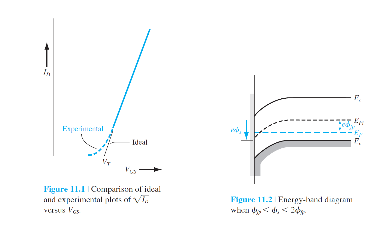
11.2中情况:weak inversion
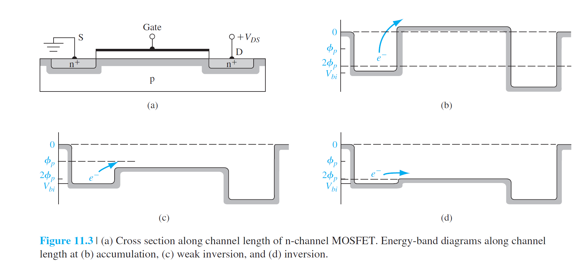
\[
I_D(sub)\propto [\exp(\frac{eV_{GS}}{kT})]\cdot[1-\exp(\frac{-eV_{DS}}{kT})]
\]
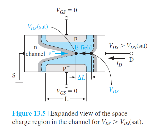
1.2 Channel Length Modulation
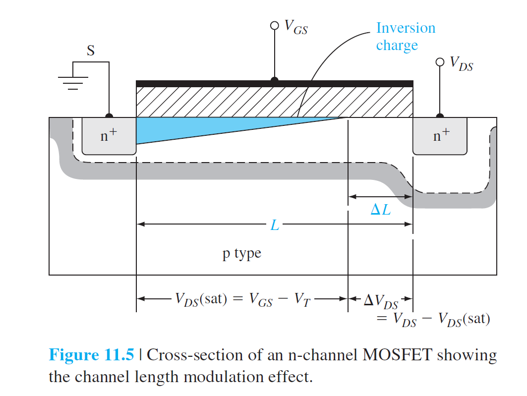
\[
x_p=\sqrt{\frac{2\epsilon_s\phi_{fp}}{eN_a}}
\]
\[
x_p=\sqrt{\frac{2\epsilon_s}{eN_a}(\phi_{fp}+V_{DS})}
\]
\[
\Delta L=\sqrt{\frac{2\epsilon_s}{eN_a}}\left(\sqrt{(\phi_{fp}+V_{DS}(sat)+\Delta V_{DS})}-\sqrt{\phi_{fp}+V_{DS}(sat)}\right)
\]
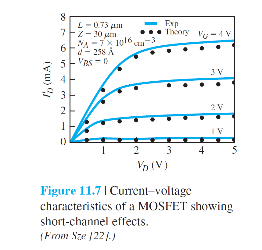
\[
I_D'=\left(\frac{L}{L-\Delta L}\right)I_D
\]
1.3 Mobility Variation
\[
E_\text{eff}=\frac1{\epsilon_s}\left( \abs{Q'_{SD}(max)}+\frac1{2}Q'_n \right)
\]
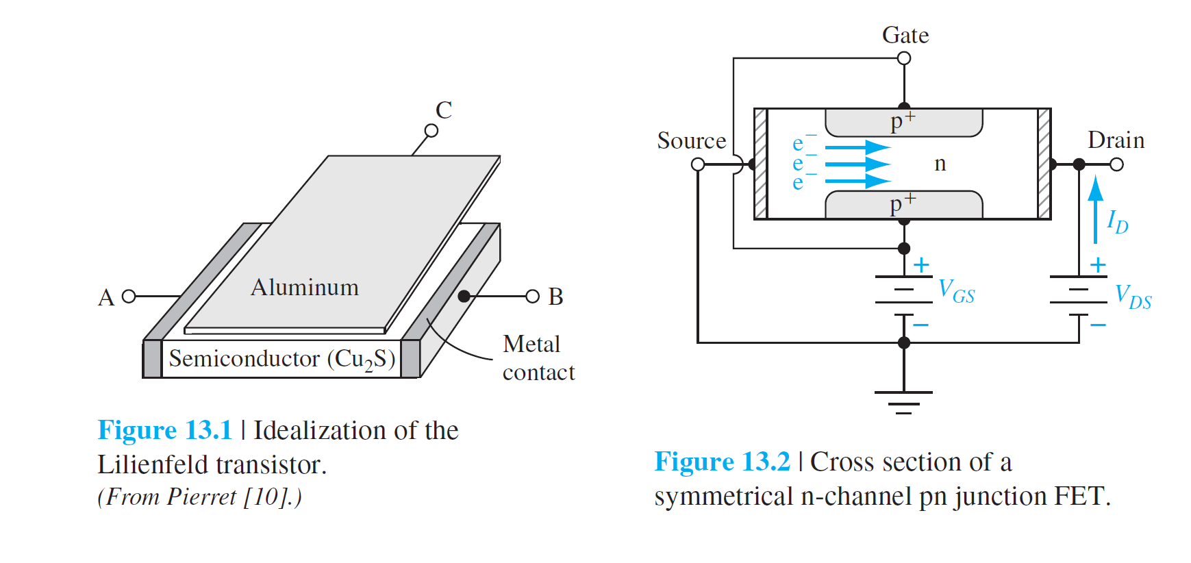
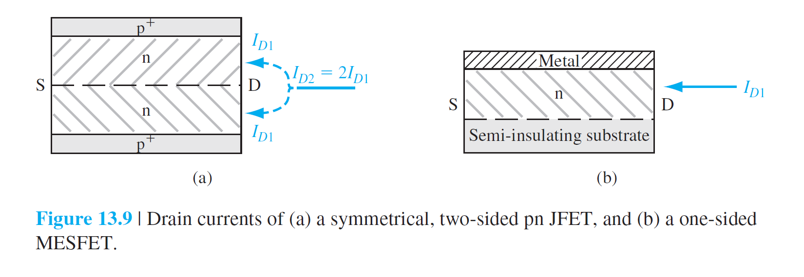
JFET MESFET The Junction Field-Effect Transistor
Basic pn JFET Operation
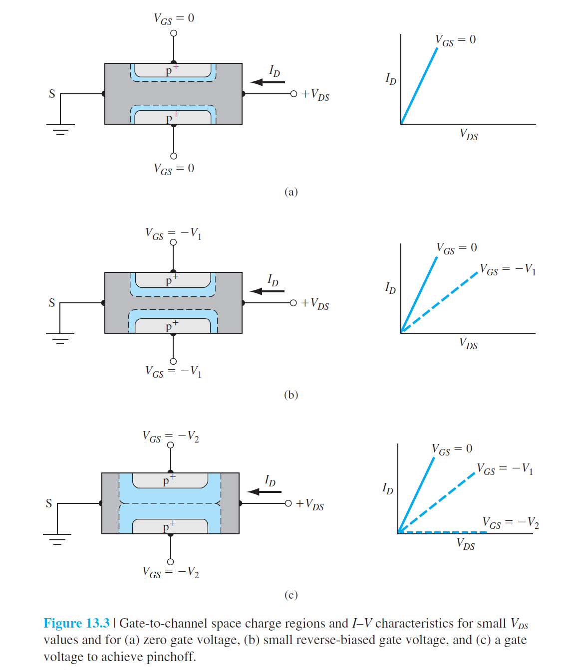

Basic MESFET Operation
The Device Characteristic
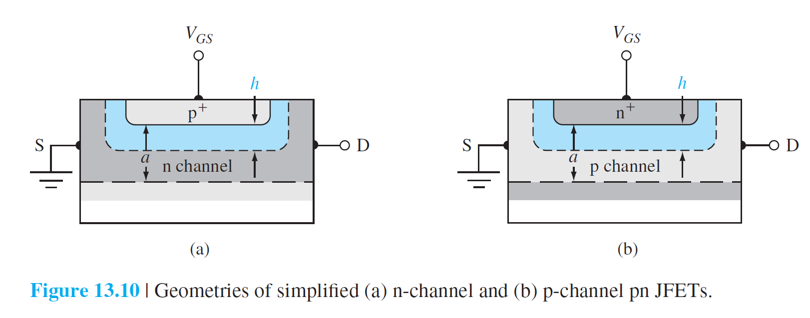
\[
h=\sqrt{\frac{2\epsilon_s(V_{bi}-V_{GS})}{eN_d}}
\]
阈值点:\(h=a\),\(\text{p}^+\text{n}\)结的总电势称为内建夹断电压,\(V_{p0}\)
\[
a=\sqrt{\frac{2\epsilon_sV_{p0}}{eN_d}}
\]
\[
V_{p0}=\frac{ea^2N_d}{2\epsilon_s}
\]
\(V_{p0}\)不是阈值栅源电压,形成沟道夹断栅源电压为夹断电压\(V_p\)
\[
V_{bi}-V_p=V_{p0}\text{ 或 }V_p=V_{bi}-V_{p0}
\]


